Lab Note
The Humble Breadboard
A first practical look at solderless breadboards, including what I learned by checking the internal connections with a multimeter instead of assuming every board was wired the same way.
As I work on learning electronics, I have been slowly accumulating the bits and pieces that will eventually become a functional workbench. Setting up a workbench and collecting the right tools is a project all by itself, especially when you are still learning what you actually need.
At first, I started with a soldering station. That made sense to me because learning electronics meant building things, and building things seemed like it would eventually require soldering parts together. It felt a little like wanting to build a fence and thinking the first thing you need is a hammer.
I had the soldering iron, and I had purchased a few small starter kits with LEDs, capacitors, and other basic parts. But once I had the parts in front of me, I realized that soldering things together while I was still trying to understand them did not make much sense.
I needed to step back.
That led me to the breadboard.
Why the Breadboard Matters
My goal is to understand what each electrical component is, what it does, and how it is used. From there, I want to apply that knowledge to build useful things for my radio projects.
A solderless breadboard gives me a way to experiment with components individually, and then as part of a circuit, without having to solder everything together first or hold parts in my hands while trying to test them.
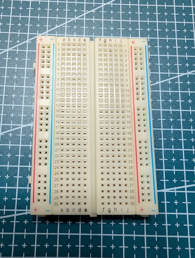
At first glance, a breadboard looks simple enough. It is a piece of plastic with holes that hold parts in place. What I did not realize at first was that there is a hidden connection system underneath the surface.
The center area is usually divided by a gap. The holes on each side of that gap are connected in small groups, which makes it possible to place parts across the gap and connect other components or jumper wires to them.
The long rails on the sides are usually used for power, but this is where I learned my first important lesson:
Do not assume every breadboard is connected the same way.
Checking the Connections
For my learning style, it helps to try things for myself. I can read about something for hours, but once I see it work with my own tools, it sticks better.
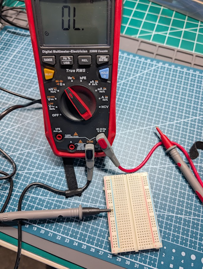
To understand the breadboard layout, I used my multimeter in continuity mode. In continuity mode, the meter beeps when two points are electrically connected. That makes it a simple way to map out what is connected inside the board.
I checked across the center area first. On all of the breadboards I tested, the center divider separated the two sides of the board. The physical indentation in the plastic made this easy to see, but testing it with the meter confirmed it.
Then I checked the power rails.
That is where things got more interesting.
The Rail Assumption That Was Wrong
The columns on either side of the board, usually called power rails or power buses, look like they run the full length of the breadboard. I assumed they were connected all the way from one end to the other.
My measurements showed that assumption was not always true.
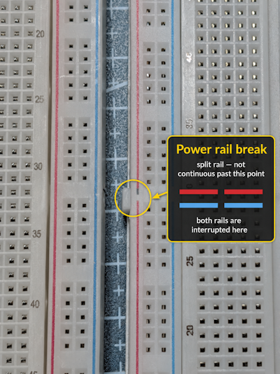
On some boards, the power rails do run the full length of the board. On others, the rails are split into separate sections. That can create four separate rail areas instead of two long rails.
After noticing that, I looked closer at the markings on the boards. The clue was right there, but it would have been easy to miss.
On one board, the red and blue rail markings were solid and unbroken, which matched the continuity test. On another board, there was a small gap in the printed red and blue lines. That gap marked where the rail was split.
Why Split Rails Can Be Useful
At first, split rails seemed like a problem. But after looking into it, they started to make sense.
A split rail can be useful when a circuit needs more than one voltage. For example, part of a project may need 3.3 V while another part needs 5 V. With split rails, those supplies can both be available on the breadboard while remaining separated.
That is useful, but only if you know the rails are split.
If you assume the rail is continuous and it is not, part of the circuit may not receive power. If you assume the rail is split and it is actually continuous, you could accidentally connect two supplies together. Neither mistake is something I want to discover the hard way.
Lesson Learned
The breadboard is simple, but it is not magic. It has an internal layout, and that layout matters.
Taking a few minutes to check the board with a multimeter helped me understand what was actually happening under the plastic. That small step should make me less likely to make frustrating or costly mistakes later.
For now, the practical rule is simple:
Before building on an unfamiliar breadboard, check the rail layout with a meter.
In the future, I will probably learn that breadboards introduce unwanted effects in some circuits, especially as I get into faster signals, RF, or more sensitive analog work. I will deal with that when I get there.
For today, the humble breadboard earned its place on the bench.
Until next time, 73 from the lab.
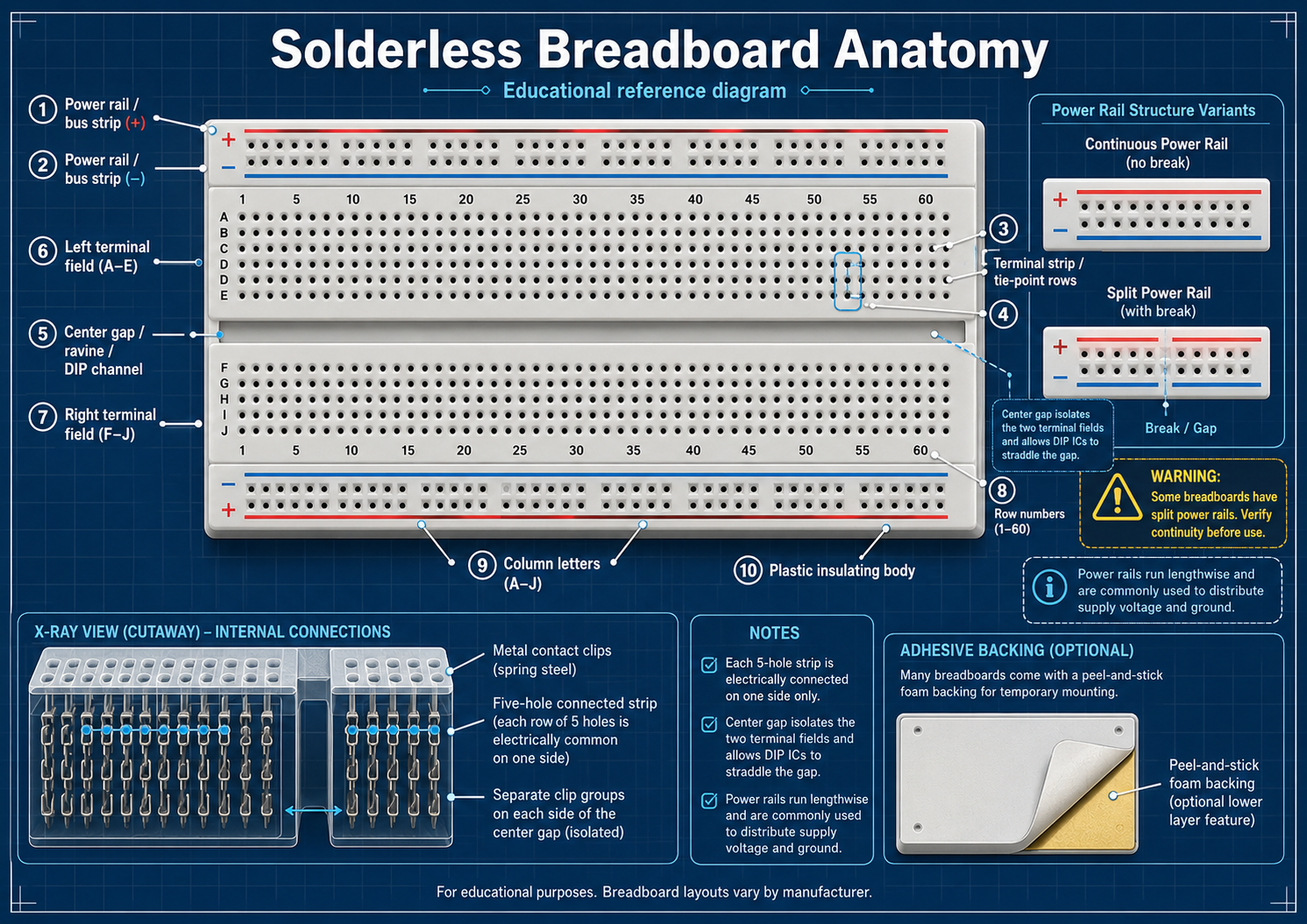
The reference diagram below shows a common solderless breadboard layout: center terminal strips are connected in short rows on each side of the center gap, while the side power rails may be continuous or split. Check an unfamiliar board with continuity mode before relying on the rail markings.
Feedback
Found a mistake or have feedback?
Desert Radio Labs is a learning project. Corrections, better test methods, shared results, and thoughtful suggestions are welcome.
Email: feedback@desertradiolabs.com