Lab Note
Testing the UNI-T UTP3315TFL-II Bench Power Supply
Initial bench validation of a new UNI-T UTP3315TFL-II bench power supply before the return window closed, including voltage checks, simple load testing, and first observations.
Evidence and limits
TestedChecked in a bench or controlled setup; field performance is not implied.
Observed
- The supply showed no obvious physical, thermal, smell, or operational warning signs during the first bench session.
- The power supply fan ran continuously, which was expected for this unit.
Measured
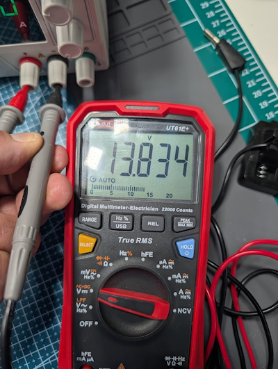
- The 3.3 V no-load setting measured 3.31 V with a UNI-T UT61E+ multimeter.
- The 5.0 V no-load setting measured 5.12 V with a UNI-T UT61E+ multimeter.
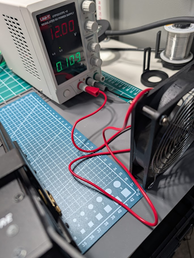
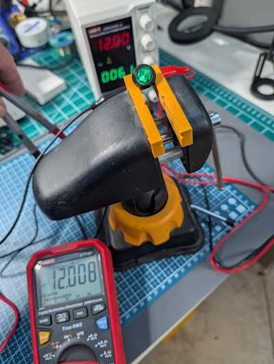
- A 12.0 V computer-fan load measured 12.008 V.
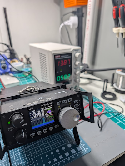
- A 13.87 V supply setting showed 13.8 V on the Xiegu G90 radio display.
Not measured or uncertain
- The supply was not tested to its full 30 V / 5 A rating.
- Long-term reliability, current limiting behavior, and output noise or ripple were not measured in this first check.
I bought a new UNI-T UTP3315TFL-II bench power supply to use with the electronics projects I will be working on.
Since I purchased it through Amazon and the return window was getting close, I wanted to do a basic bench validation before the window closed. The goal was not to do a full lab-grade review. I just wanted to make sure the supply worked correctly, held voltage under simple loads, did not show obvious physical issues, and did not produce any early warning signs like heat, smell, or unstable output.
Supply under test
The supply tested was the **UNI-T UTP3315TFL-II**, a single-channel linear DC bench power supply rated for up to **30 V / 5 A**.
This is intended to become one of the main bench tools for future electronics work, including small circuits, radio-related projects, fans, modules, and test setups.
Test goal
The goal of this first test was simple:
- Inspect the supply and included leads
- Confirm basic output voltage settings
- Compare the supply output against a handheld multimeter
- Run a few simple DC loads
- Watch for heat, smell, fan behavior, voltage stability, or other obvious problems
- Decide whether the power supply appeared safe and reasonable to keep before the return window closed
This was a practical acceptance test, not a full technical review.
Equipment used
- UNI-T UTP3315TFL-II bench power supply
- UNI-T UT61E+ digital multimeter
- Included banana plug to alligator clip test leads
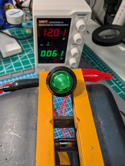
- 12 V warning light
- 12 V computer fan
- Xiegu G90 radio
- Homemade radio power adapter with Anderson Powerpole connectors on one end and ring terminals on the other
- G90 cooling fan base
Setup
I set the power supply up on the bench using the included banana plug test leads with alligator clips on the output end.
For the first simple checks, I connected small 12 V loads directly to the power supply using the included leads.
For the radio test, the Xiegu G90 was connected through a homemade adapter. The radio side used Anderson Powerpole connectors, and the bench supply side used ring terminals. The alligator clips from the power supply leads were clipped to the ring terminals.
The G90 was also sitting on a cooling fan base. That fan runs continuously when the radio is connected to power, so the supply was powering the fan before the radio itself was turned on.
Before applying power to the radio, I checked polarity.
Safety notes
This was a low-complexity bench test, but there were still a few things worth paying attention to.
Alligator clips are convenient, but they are not my preferred long-term connection method for radio equipment or higher-current bench work. They can slip, short, or grab more exposed metal than intended. For this test, I kept the setup controlled and watched it closely.
The homemade radio power adapter also made polarity checking important. Before powering the G90, I verified that positive and negative were correct.
This was not a stress test or a destructive test. I did not try to push the supply to its full 30 V / 5 A rating. The goal was only to confirm that the supply behaved normally under the kind of light-to-moderate loads I am likely to use early on.
Voltage checks
I checked the output voltage using a UNI-T UT61E+ multimeter.
The supply was checked at several useful voltage points:
| Set Voltage | Measured Voltage | Load | Result |
|---|---|---|---|
| 3.3 V | 3.31 V | No load | Pass |
| 5.0 V | 5.12 V | No load | Pass |
| 12.0 V | 12.008 V | Computer fan | Pass |
| 13.87 V supply display | 13.8 V radio display | Xiegu G90 and cooling fan base | Pass |
All measured values appeared to be within a reasonable tolerance for this kind of bench acceptance test.
Load tests
I tested the supply with a few simple loads that represent realistic things I may power from the bench.
| Load | Voltage | Duration | Result |
|---|---|---|---|
| 12 V warning light | 12.0 V | 15 minutes | Pass |
| 12 V computer fan | 12.0 V | 15 minutes | Pass |
| Xiegu G90 with cooling fan base | 13.8 V | 60 minutes | Pass |
The power supply handled these loads without any obvious trouble.
During the G90 test, the cooling fan base was already drawing power before the radio was turned on. The supply handled the change in load when the radio was powered up, and I did not notice any concerning behavior.
Observations
The supply looked good out of the box. The case, front panel, controls, display, and included leads did not show any obvious physical problems.
The included test leads were packaged cleanly and appeared to be in good condition.
During the test, the power supply fan ran continuously. That was expected behavior for this unit.
I did not notice any electronic smell, overheating, or concerning temperature change during the test. The supply ran smoothly through the checks I performed.
Result
The UNI-T UTP3315TFL-II passed my initial bench validation.
The voltage checks looked good, the simple load tests passed, and the supply did not show any obvious physical, thermal, or operational problems during this first test session.
That is enough for me to keep it and start using it as a normal bench supply for upcoming electronics work.
What this test does not prove
This test does not prove long-term reliability.
I did not test this as deeply as someone with a full electronics bench could. This was a practical first check using the tools I currently have.
For now, this was enough to answer the question I had before the return window closed: does this supply appear to work normally for the kind of beginner bench work I am about to do?
Next steps
The next useful steps are:
- Use the supply on real beginner bench projects
- Test current limiting behavior in a controlled setup
- Eventually measure output noise or ripple if I add the right equipment
Until next time, 73 from the lab.
Feedback
Found a mistake or have feedback?
Desert Radio Labs is a learning project. Corrections, better test methods, shared results, and thoughtful suggestions are welcome.
Email: feedback@desertradiolabs.com