The Rybakov Antenna
A simple non-resonant vertical wire antenna using a 25-foot radiator, counterpoise, four-to-one unun, common-mode choke, coax, and tuner.
Article
A beginner-friendly explanation of what a 4:1 unun does, how it differs from a common-mode choke, and why it is useful in portable HF antennas like the Rybakov.
When I first started learning about HF antennas, I saw the terms balun, unun, choke, tuner, counterpoise, and matching transformer thrown around like everyone already knew exactly what they meant. I did not.
I understood the basic idea that my radio wanted to see something close to 50 ohms. I also understood that random wires, verticals, counterpoises, and portable antennas could be all over the place electrically. What I did not understand was where each little box or toroid fit into the system.
The Rybakov-style antenna pushed me to learn more about this because the setup is so simple on the surface: a vertical wire, a counterpoise, a 4:1 unun, coax, a common-mode choke, and a tuner. That looks simple enough to build and use, but once I started trying to understand what each part actually does, I realized there is more going on than just “wrap some wire around a toroid.”
This article is my attempt to explain the 4:1 unun in plain language. This is not a construction guide yet. Before I write a build article, I want to understand what the device is supposed to do, what it is not doing, and why it belongs in the antenna system.
A 4:1 unun is an impedance transformer.
It does not tune the antenna by itself. It does not prove that the antenna is resonant. It does not guarantee that the antenna is efficient. Its job is to transform the impedance at the antenna feedpoint into a range that may be easier for the coax, tuner, and radio to work with.
In a simple example, a 4:1 unun can make something around 200 ohms on the antenna side look closer to 50 ohms on the coax side. Real antennas are messier than that, especially multiband non-resonant antennas, but that simple example gives the basic idea.
A common-mode choke is different. A choke is used to reduce unwanted RF current on the outside of the coax shield. A 4:1 unun transforms impedance. A 1:1 common-mode choke controls unwanted feedline current. They may both use ferrite cores, but they are doing different jobs.
The word unun means unbalanced to unbalanced.
That matters because coax is an unbalanced feedline. It has a center conductor and a shield. The current paths are not symmetrical in the same way they would be in a balanced feedline like ladder line.
A vertical antenna with a counterpoise is also usually treated as an unbalanced antenna system. There is a radiator side and a return side. In a Rybakov-style antenna, the vertical wire is the radiator, and the counterpoise or radial system provides the return path.
That makes a 4:1 unun a reasonable device to place between the coax and the antenna system. It is not trying to convert from balanced to unbalanced. It is trying to transform impedance between two unbalanced systems.
The “4:1” part refers to impedance transformation.
In the simplified textbook version, a 4:1 unun can transform impedance by a factor of four. So an antenna-side impedance around 200 ohms can look closer to 50 ohms at the coax side.
That does not mean the antenna is always 200 ohms. It also does not mean the radio will automatically see a perfect match on every band. Real antenna impedance changes with frequency, wire length, height, counterpoise layout, ground conditions, nearby objects, and many other things.
The useful idea is this: the 4:1 unun may move the feedpoint impedance into a range that is easier for the tuner to handle.
For a non-resonant multiband antenna, that can sometimes be the difference between a tuner finding a usable match or struggling.
A Rybakov-style antenna is commonly built as a non-resonant vertical wire antenna. A common portable version uses a vertical radiator around 25 feet long, a 4:1 unun at the feedpoint, and some kind of counterpoise or radial system. A tuner is still normally required.
That is the key point: the 4:1 unun is not replacing the tuner.
Instead, the system works more like this:
Radio and tuner send RF through the coax. The coax reaches the 4:1 unun at the feedpoint. The unun transforms the impedance between the coax side and the antenna side. The vertical wire and counterpoise do the actual radiating and return-path work. The tuner handles the final match that the radio sees.
In plain language, the 4:1 unun helps the antenna system become more manageable.
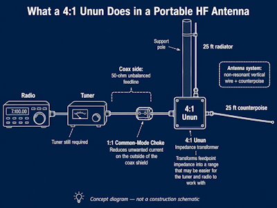
_Concept diagram showing where the 4:1 unun fits in the antenna system. This is not a construction schematic._
This was one of the places I got confused.
A common-mode choke can also be made by wrapping coax around a toroid or passing coax through ferrite. That looks similar from the outside because both devices may involve ferrite and turns of wire or coax. But the job is different.
A common-mode choke is trying to stop unwanted current from flowing on the outside of the coax shield. That outside-of-the-shield current can make the coax act like part of the antenna. Sometimes that changes tuning. Sometimes it brings RF back toward the radio. Sometimes it increases noise pickup. Sometimes it causes weird behavior that is hard to troubleshoot.
A 4:1 unun is not mainly trying to block current. It is trying to transform impedance.
That distinction helped me a lot:
Those three things work together, but they are not the same thing.
The winding is where this topic starts to feel mysterious.
With a simple choke, the mental model is fairly easy. You wrap coax through ferrite, and the ferrite presents impedance to common-mode current.
With a 4:1 unun, the winding is part of a transformer. Depending on the design, there may be two wires wound together, multiple cores, or a transmission-line transformer arrangement. The number of turns matters, but the way the wire ends are connected matters just as much.
That is why a picture of colored wires around a toroid can help explain the concept, but it is not automatically a construction blueprint.
To build one correctly, you need both:
Without the schematic, the winding picture is incomplete.
A 4:1 unun is simple in concept, but it is still possible to build one badly.
The wrong core material may perform poorly on the bands you care about. Too few or too many turns may affect bandwidth or efficiency. Thin wire or a small core may heat up at higher power. Incorrect lead connections can produce the wrong transformer behavior entirely. A design that works fine at low power may not be appropriate for 100 watts, especially with high-duty-cycle digital modes or a difficult antenna load.
It is also easy to give the unun too much credit. A good SWR at the radio does not prove that the antenna is efficient. It only tells you that the radio is seeing a match it can tolerate. Power can still be lost in the transformer, tuner, coax, ground system, or surrounding environment.
That does not make the 4:1 unun bad. It just means it should be understood as one part of the system.
The next step is to choose a generic 100-watt-class 4:1 unun reference design and document it clearly.
I do not want to copy a commercial product. The goal is not to reverse-engineer the unun I already own. The goal is to understand the circuit well enough to build a beginner-friendly homebrew version using common parts, clear schematics, and honest testing.
The build article should include:
Before I build it, I want to be able to explain it. That is the real goal.
The 4:1 unun is not magic. It is not a tuner, and it does not make a non-resonant antenna suddenly resonant. It is an impedance transformer that can make a practical portable antenna system easier to match and use.
For me, understanding that difference is the first step toward building one with confidence instead of just copying a diagram and hoping it works.
Until next time, 73 from the lab.
Feedback
Desert Radio Labs is a learning project. Corrections, better test methods, shared results, and thoughtful suggestions are welcome.
Email: feedback@desertradiolabs.com